


MDG Integration for Microsoft Office – Excel BPMN Visualizer
The latest MDG Office Integrations (v1.4.40) provides an enrichment feature named “BPMN Visualizer,” which allows the user to push the BPMN elements from the Microsoft Excel document into Sparx Enterprise Architect Model and vice versa.
Key Features of BPMN in MDG Office Integration
- Simplified Approach that eliminates the necessity for Profile Creation during import and export for mapping items. This drastically minimizes user time and the possibility of manual errors.
- Through a single click of “Excel to EA” menu, users can quickly synchronize BPMN Elements, seamlessly updating and aligning data between Excel and the Enterprise Architect model.
- The visual representation of diagrams from the EA model, as well as the related preconfigured mapping table, can be displayed within Excel.
- The capability to incorporate multiple diagrams is supported when a package is selected. This means that all diagrams within the chosen packages are exhibited, accompanied by their respective predefined mapping tables in separate sheets.
To import BPMN data into Enterprise Architect from Excel
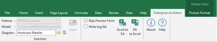
Figure 1 – Excel Ribbon
BPMN Visualizer in Excel Interface
| ‘BPMN Visualizer’: Import and Export between Excel and Enterprise Architect of BPMN element and their connectors. | |
| Allows users to select a Package or BPMN Diagram to Load from the EA Model to the Excel with the respective diagram image. |
Once Enterprise Architect model is connected, the Excel sheet is loaded with diagram and its predefined mapping table.
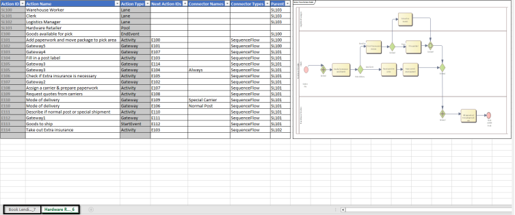
Figure 2 – BPMN Element data along with diagram
Excel column definition
The table below describes the details of the predefined columns in the Excel
| Action ID | The Unique ID of BPMN Elements. It’s used to map the connectors and parent. |
| Action Name | Name of the BPMN Element |
| Action Type | Type of the BPMN Element |
| Next Action IDs | Target BPMN Element to connect based on the Action ID. |
| Connector Name | Name of the BPMN Connector |
| Connector Type | Type of the BPMN Connector |
| Parent | The parent of a selected BPMN Element based on the Action ID. |
Note
- The Excel sheet contains only the ‘BPMN 2.0 Technology’ based Elements and Connectors.
- Format of Excel sheet name – ‘DiagramName_DiagramID’.
- The supported element types are Activity, Gateway, StartEvent, IntermediateEvent, EndEvent, DataStore, DataObject, BusinessProcess, BPELProcess, GlobalTask, Pool, and Lane.
- The supported connector types are SequenceFlow, Message Flow, ConversationLink, DataAssociation and Association.
Element and Connector Creation in Excel
- To create a new element, enter a name in the ‘Action Name’ column(mandatory). By default, the ‘Action Type’ is ‘Activity’. Users can change the type using a drop-down list.
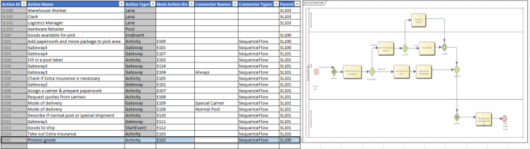
Figure 3 – Adding Element and its Connectors in Excel
- ‘Next Action ID’ creates a connector between two BPMN elements. Select the ‘Next Action ID’ checklist box and select the ‘Action ID’ to connect. By default, the connector type is ‘Sequence Flow’
- The ‘EA to Excel’ icon is used to restore the produced items to their original state as in the Enterprise Architect Model.
- After Creating Element and Connector, select the ‘Excel to EA’ icon. It will Create the new elements and connectors under the selected package in Enterprise Architect and the respective diagram is updated in the Excel sheet.
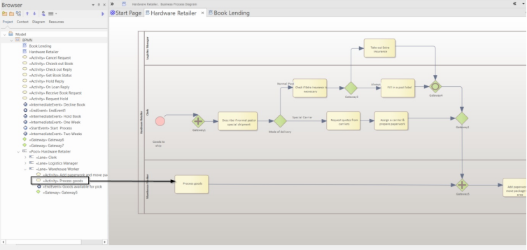
Figure 4 – Updated Element and Connector data in Enterprise Architect
Further Information
Please contact us or write an email to info@sparxsystems.in to have a live demo about the new EA 16 features and capabilities.
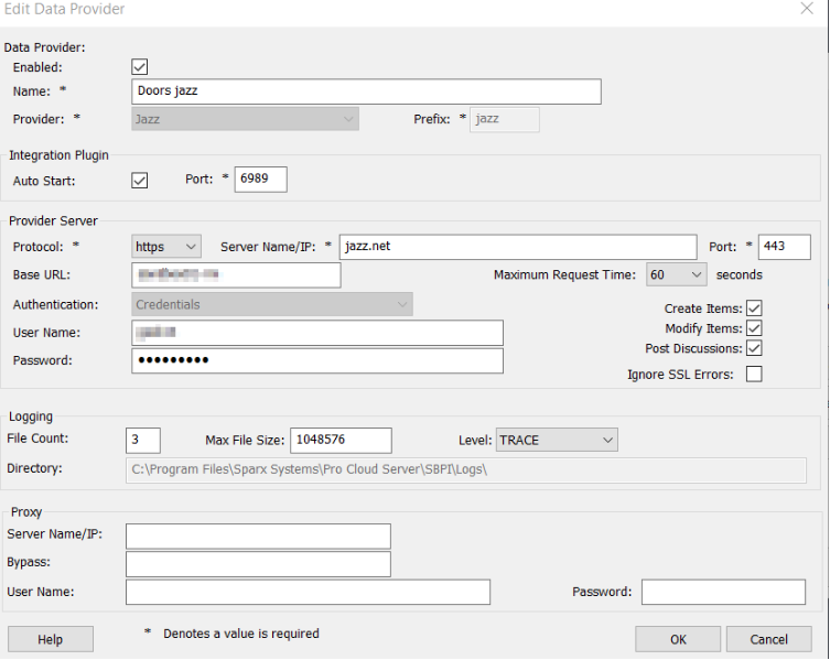
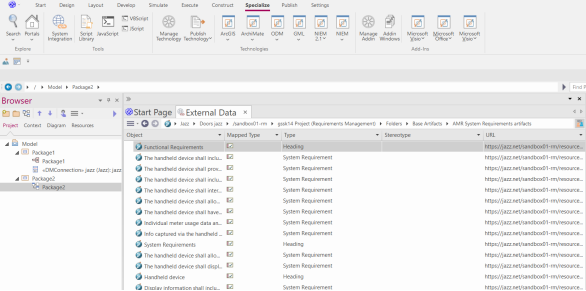
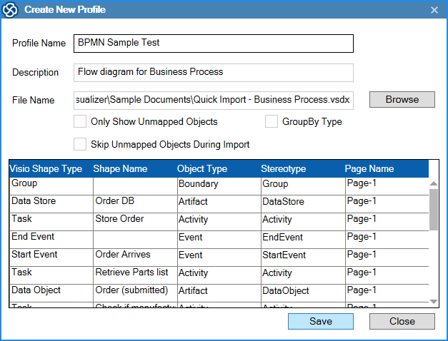
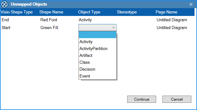
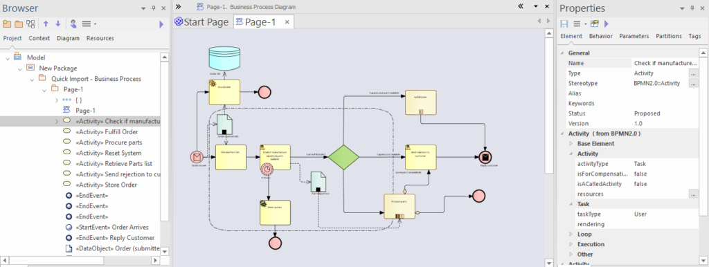
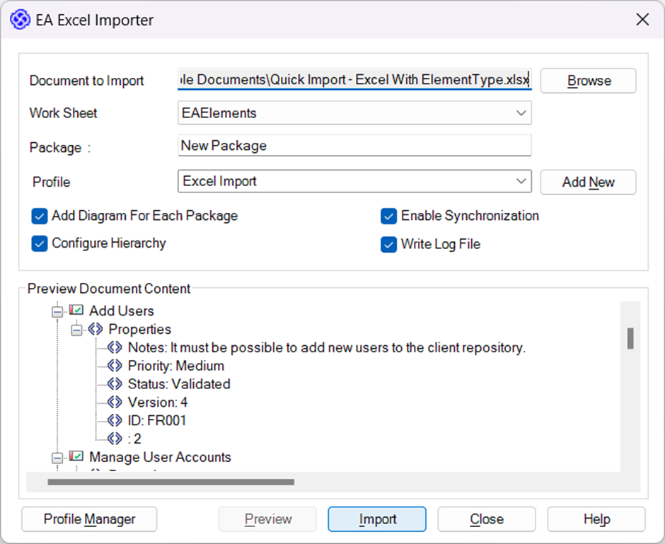
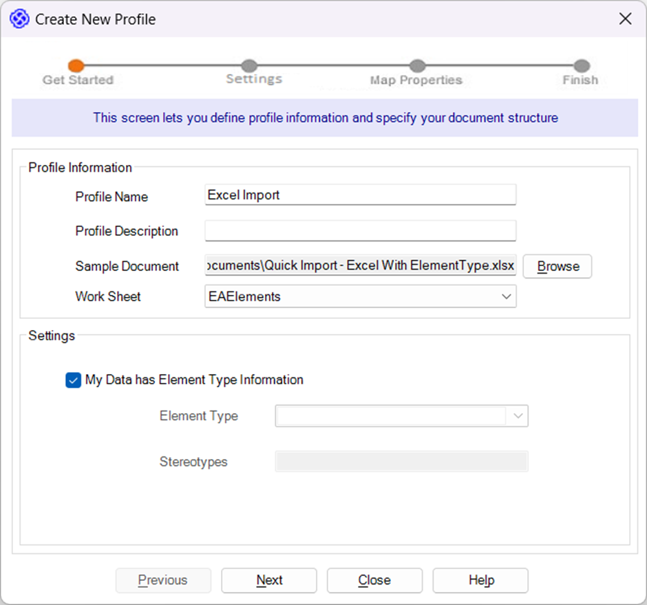

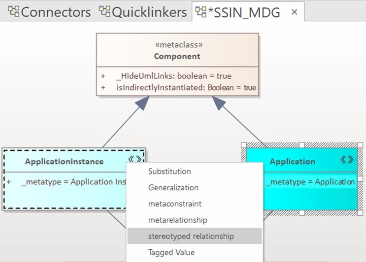
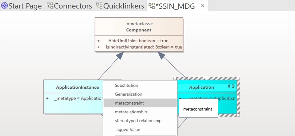
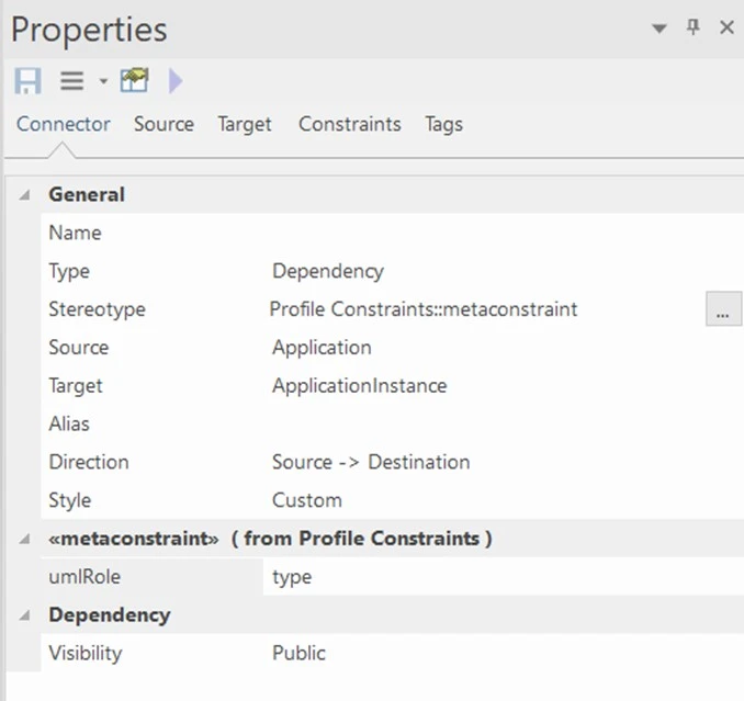
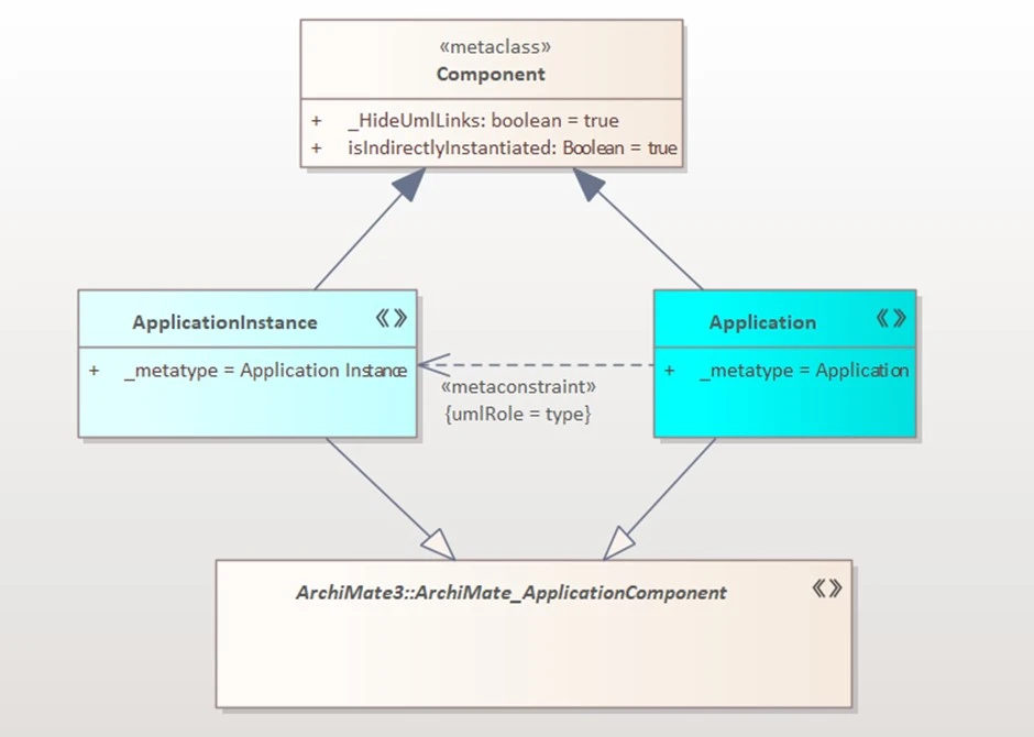
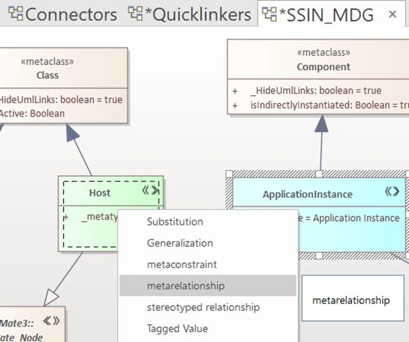
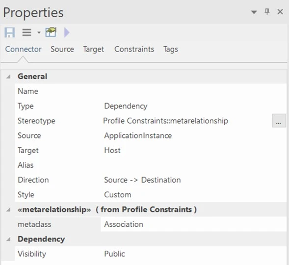
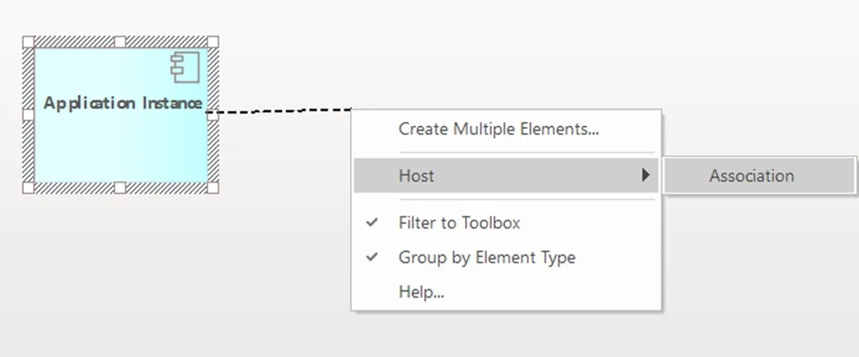
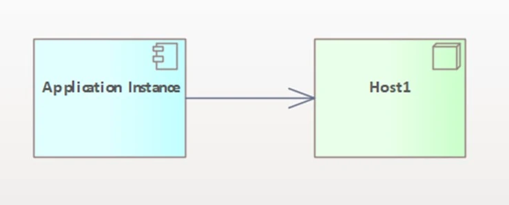
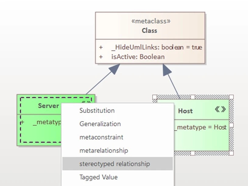
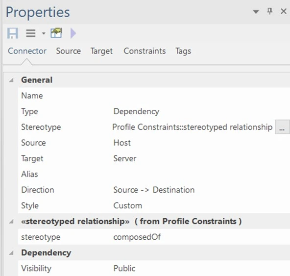
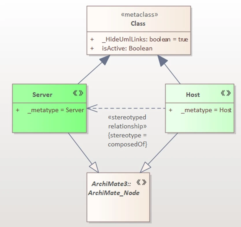
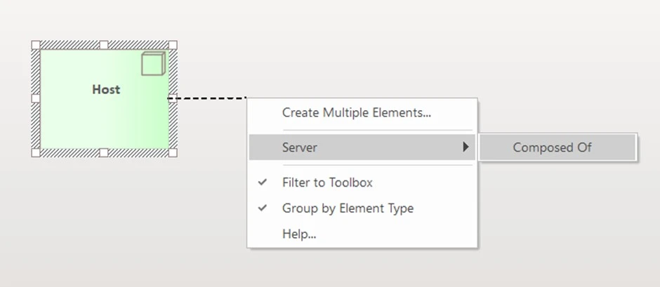
 Figure 4.4 Stereotype Relationship Created.